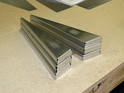
Preparing the Stabiliser Skeleton
Some of these components were 0.040 and 0.063 and I ordered them from Zenith, given the problems I’d had bending anything over 0.032 with the home made brake. Later on as I became more familiar with the processes, I devised other ways around that. I’ve since made much heavier components in my own garage.
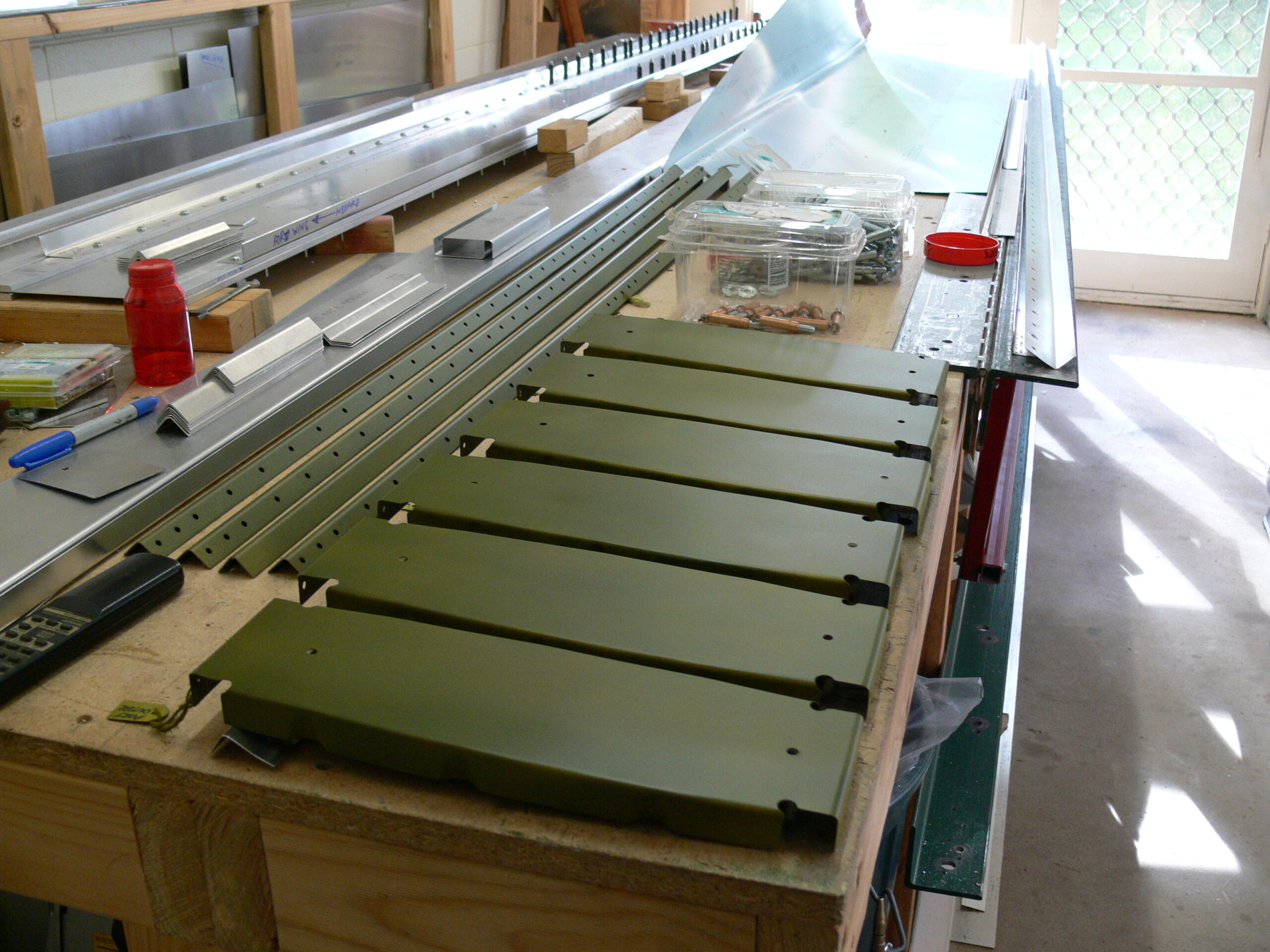
Drilling and Priming
Once the ribs were all finished, I went on to drilling the stabiliser spars. Of course I’m following the practice of pre-drilling with a 3/32” bit to align everything properly clecoing then drilling out to full size. Then it’s onto de-burring the holes to ensure a smooth surface for riveting. I primed all the stabiliser parts, including the spars and tip ribs for corrosion protection.
The doublers have to be fitted inside the spars and those areas need to be primed along with everything else, so I went ahead and primed everything. This is okay on smaller sections like this, because you’re not using a great amount of primer and you can do it with a rattle can, but I won’t be so generous with the paint on the bigger sections. It will just be applied to the joints.
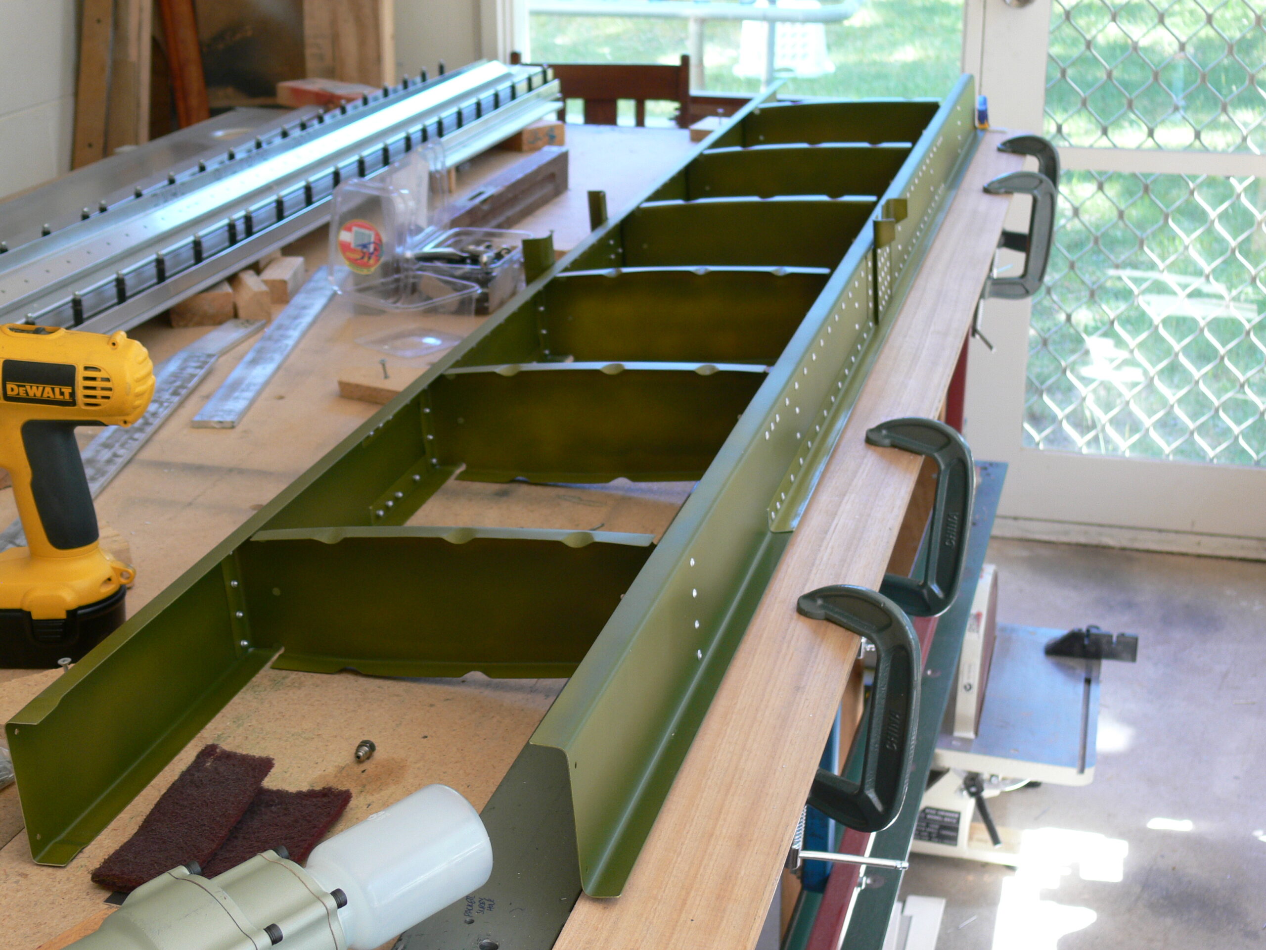
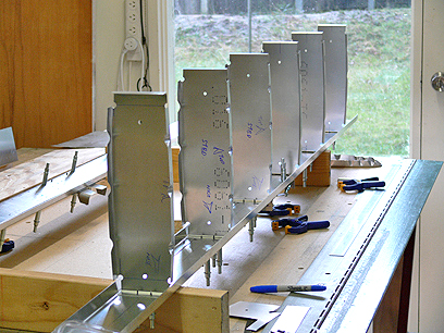
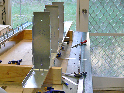
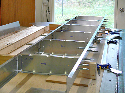
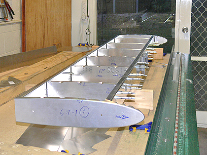
Assembling the Stabiliser Skeleton
With the parts ready, I began assembling the skeleton. Cleco it together, make sure it’s all sitting flat and level on the bench, no twisting and so on. During the assembly, I had to modifying my hand riveter to clear the top flange of the rear spar by grinding a flat on one face of the barrel. This would prove a valuable mod as the build continued.
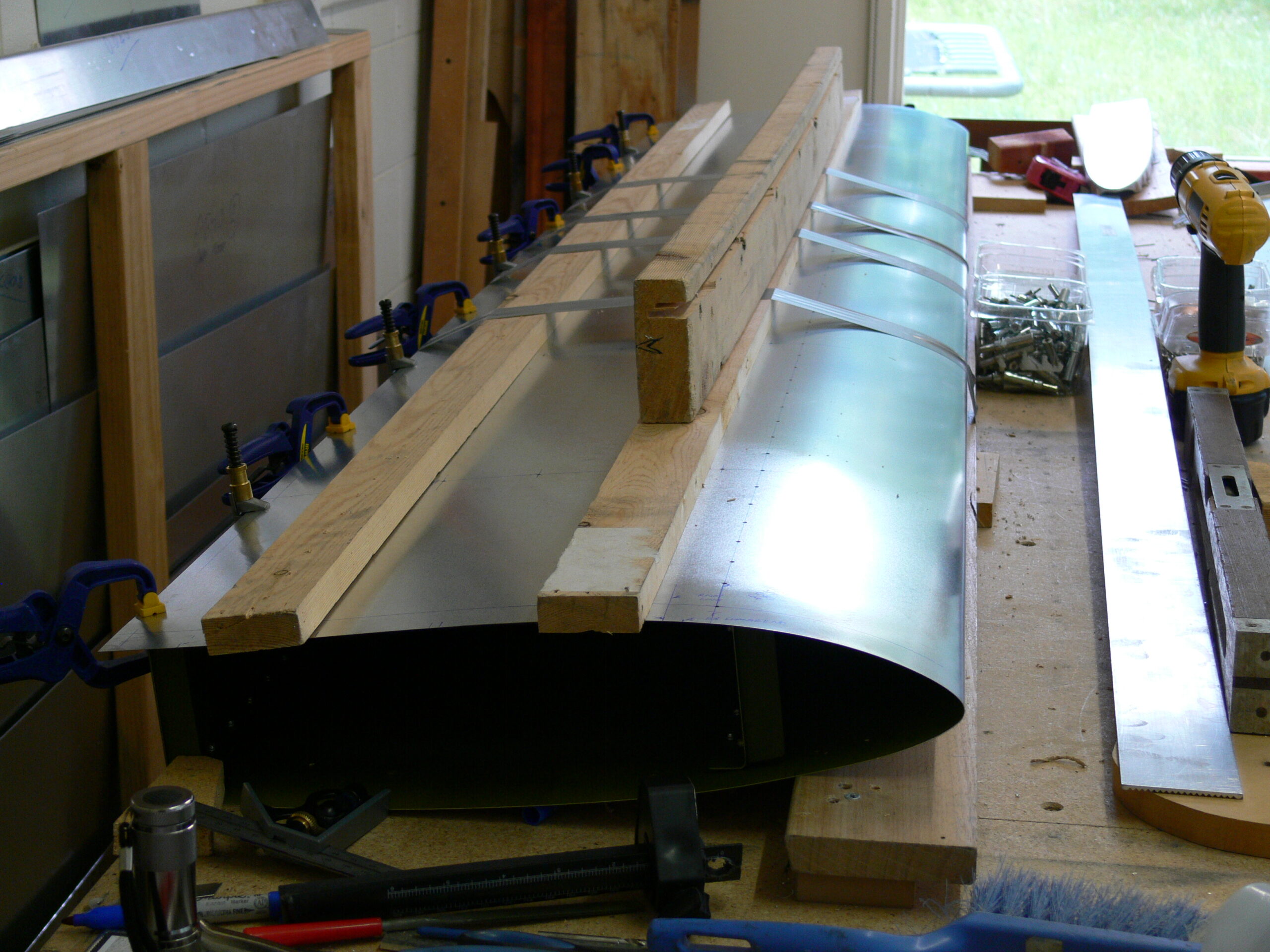
Fabricating the Stabiliser Skin
The photos show this process. The plans give you a method whereby you squash the skin under a sheet, I used a solid timber door which worked really well. You can see how I have cramped the top piece of the bending brake along the bench as a stop.
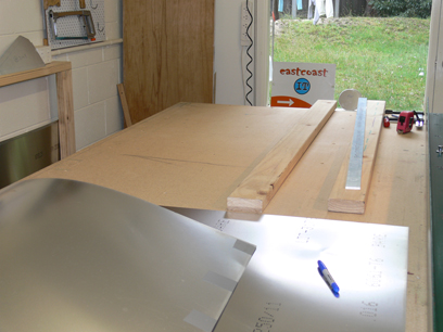
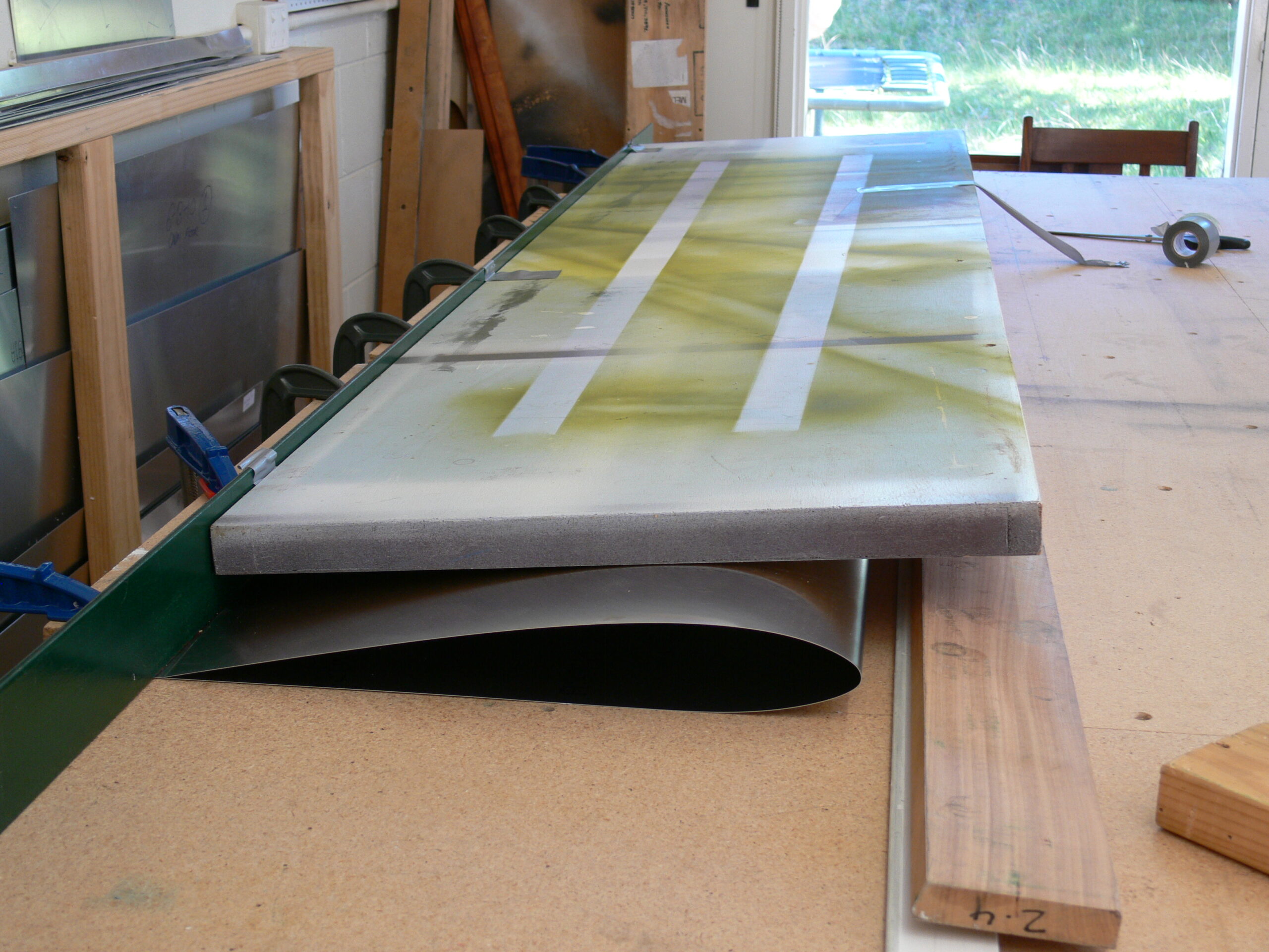
I used some lengths of timber the thickness recommended by the plans, plonked the sheet on top, got on the bench and knelt on it. Note the pieces of duct tape to stop everything sliding around.
I knew that the ends and the trailing edge may not line up correctly after folding, so I left some extra material all around, then trimmed it all to the correct size. Worked out beautiful.
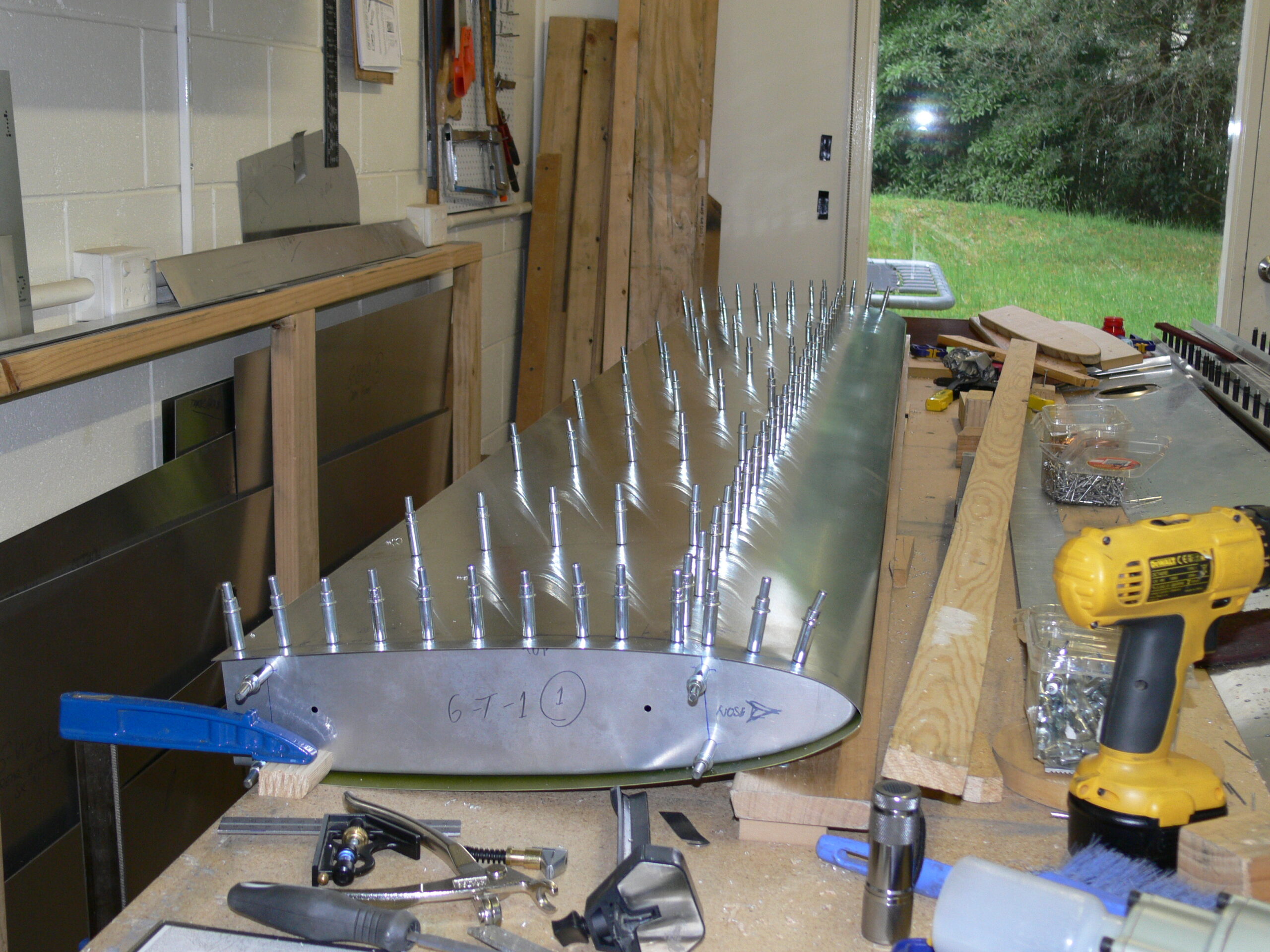
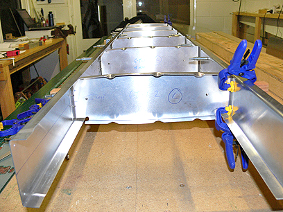
Fitting and Riveting the Stabiliser Skin
Next, I moved on to fitting the stabiliser skin. I made the cutouts in the skin as required and began fitting it into place. I pre-drilled the upper skin and set it up in place aligning the holes over the rib centre lines, clecoed, drilled, drilled out, etc., Then de-burred everything and applied primer along the join lines. I then re-assembled everything, starting with the bottom side and then moving to the top.
Note how the springy properties of 6061 aluminium necessitates holding the skin down in position with cramps, boards and duct tape.
Final Assembly Steps
The final steps of the stabiliser construction involved setting out and fitting the elevator hinge then riveting everything together. Proper alignment of the hinge is obviously important for the correct operation of the control surface, so I wanted to get it right. This remains clecoed in for now until fitting the elevator later.